Here are some notes on my book-scanner project, inspired by diybookscanner.org. This is a work in progress and will initially be a single large page and I’ll probably update it and split it into a Lessons Learned (blind alleys, problems, workarounds and eventual solutions) section at some point. If you want something I haven’t documented yet just email me: reece.arnott@gmail.com
Vision
I am planning on building a book-scanner using 3d printed parts so that the design can be easily replicated in the near future when hobbyist 3d printing becomes more widespread. I want something that is cheap and relatively easy to put together and also so you don’t have to accurately measure angles or lengths. Most of the people in the DIY book-scanner community at diybookscanner.org are using digital cameras (with either modified firmware or physical push-button devices to trigger the cameras simultaneously) but I am wanting to use UVC standards compliant webcams instead as they are cheaper and can be setup and controlled over USB and if you set the manual focus settings you can very quickly get an image without waiting for the auto-focus.
Hardware Setup
Description of Hardware
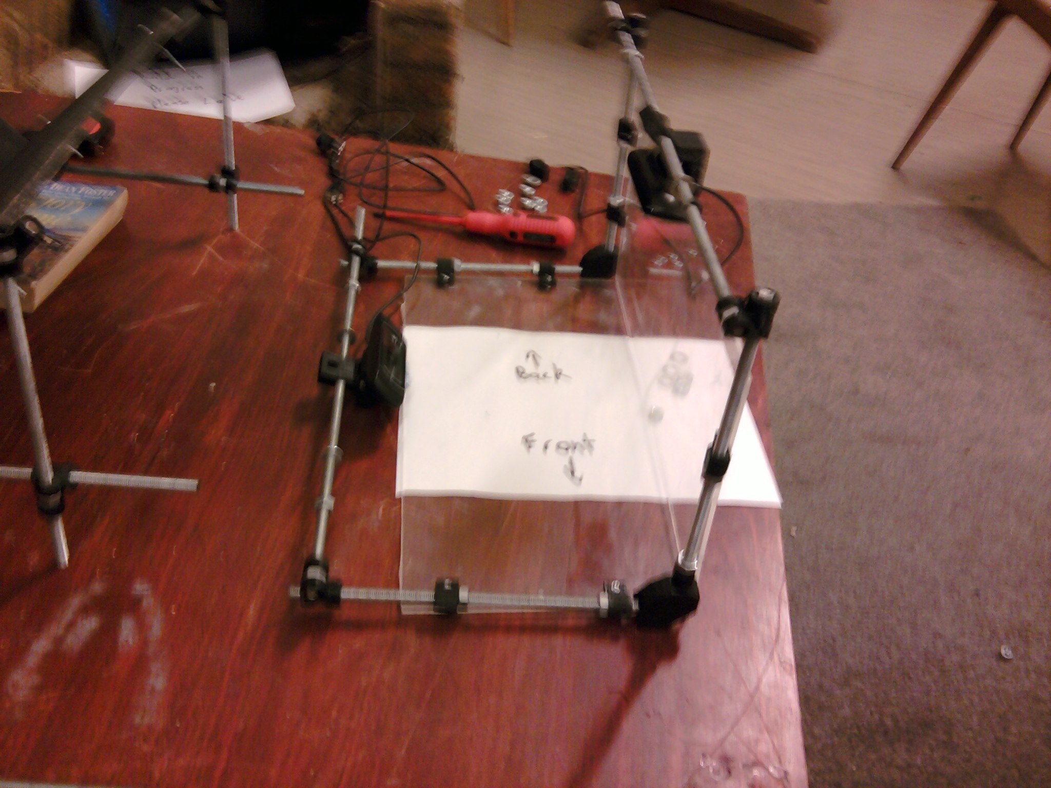
Prototype 2
Prototype 1
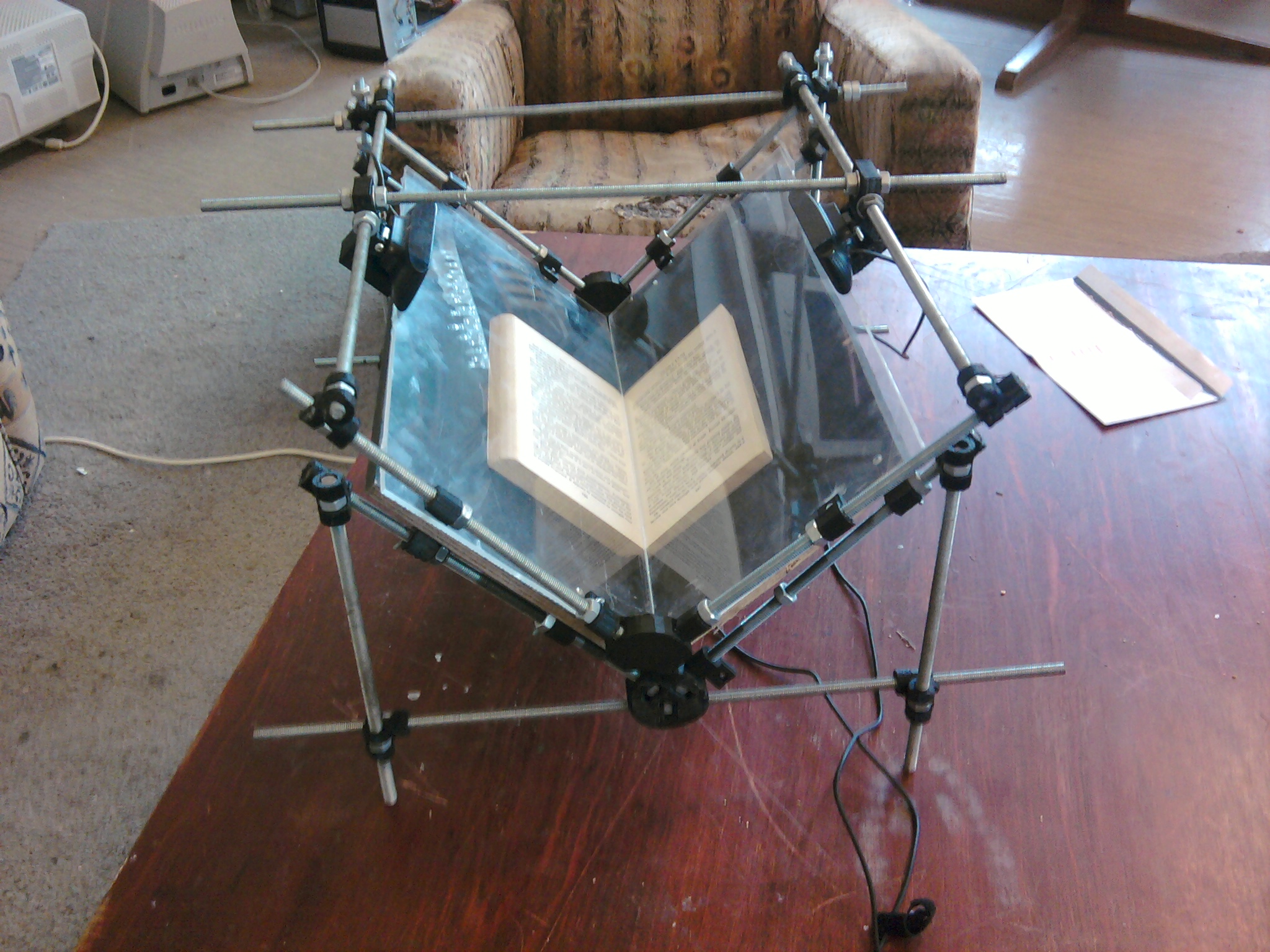
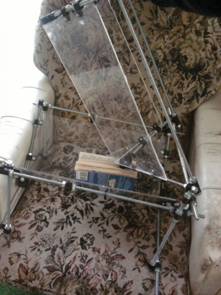
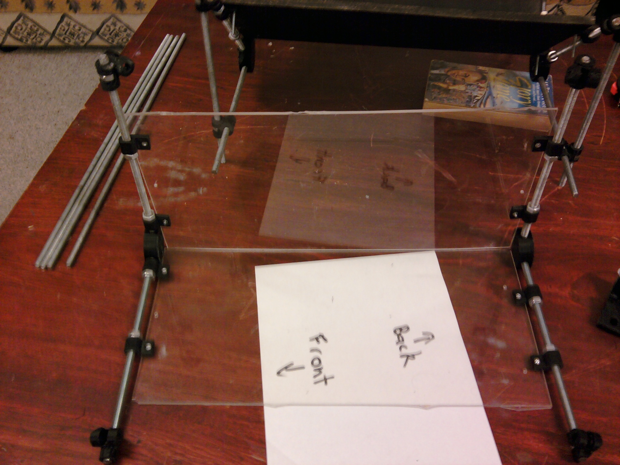
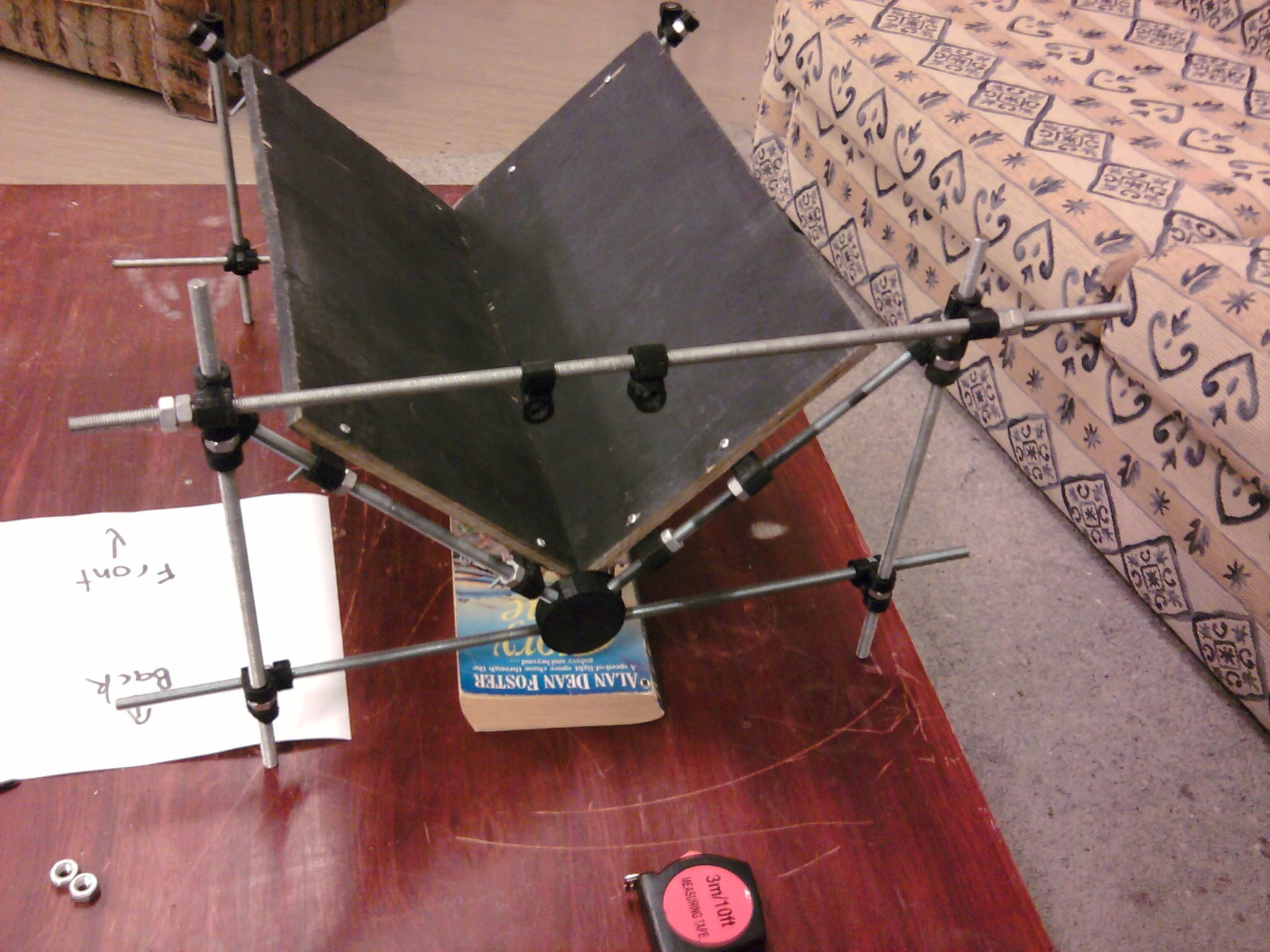
As you can see in the picture above my book-scanner is different from most others in the diy-book-scanner pantheon in that the upper-platen is hinged rather than going vertically up and down. I’m not sure if this is a better way of doing things but it is something to be explored. One thing that it does mean is that the procedure for accommodating larger books is different. In the standard models the lower platen are moved further apart until the gap between them is wide enough to fit the spine of an overly thick book. In this way the two back vertical rods could be lengthened and the hinge for the upper-platen placed further up or down the vertical rods depending on the thickness of the book, assuming the lower-platen is rigid. An additional 5cm of height equates to a book with an additional 10cm of width in the spine, probably more than enough.
For the first prototype the lower platen was made of the same perspex as the upper platen but this was found to be too flexible in the case of heavy books. It is possible that additional bracing could strengthen it but it was instead replaced with a more rigid substance: plywood. However, one advantage of perspex is that it is clear so that when making the holes that need to be drilled you can attach the printed piece to the rod and line up the hole in the 3d printed piece with the position on the perspex and just start to drill a hole on the other side of the perspex without having to measure it. Doing this with a plywood piece means that you would have to drill *through* the existing hole in the printed piece and would need finer control of the drill to make sure you didn’t damage the printed part in the process. This advantage is also a disadvantage when it comes to the actual scanning process as the automatic boundary finding processes used in the post-processing stages may find it difficult depending on what can be seen through the bottom platen. I spray painted the bottom platen black in-situ to get around this for the first prototype.
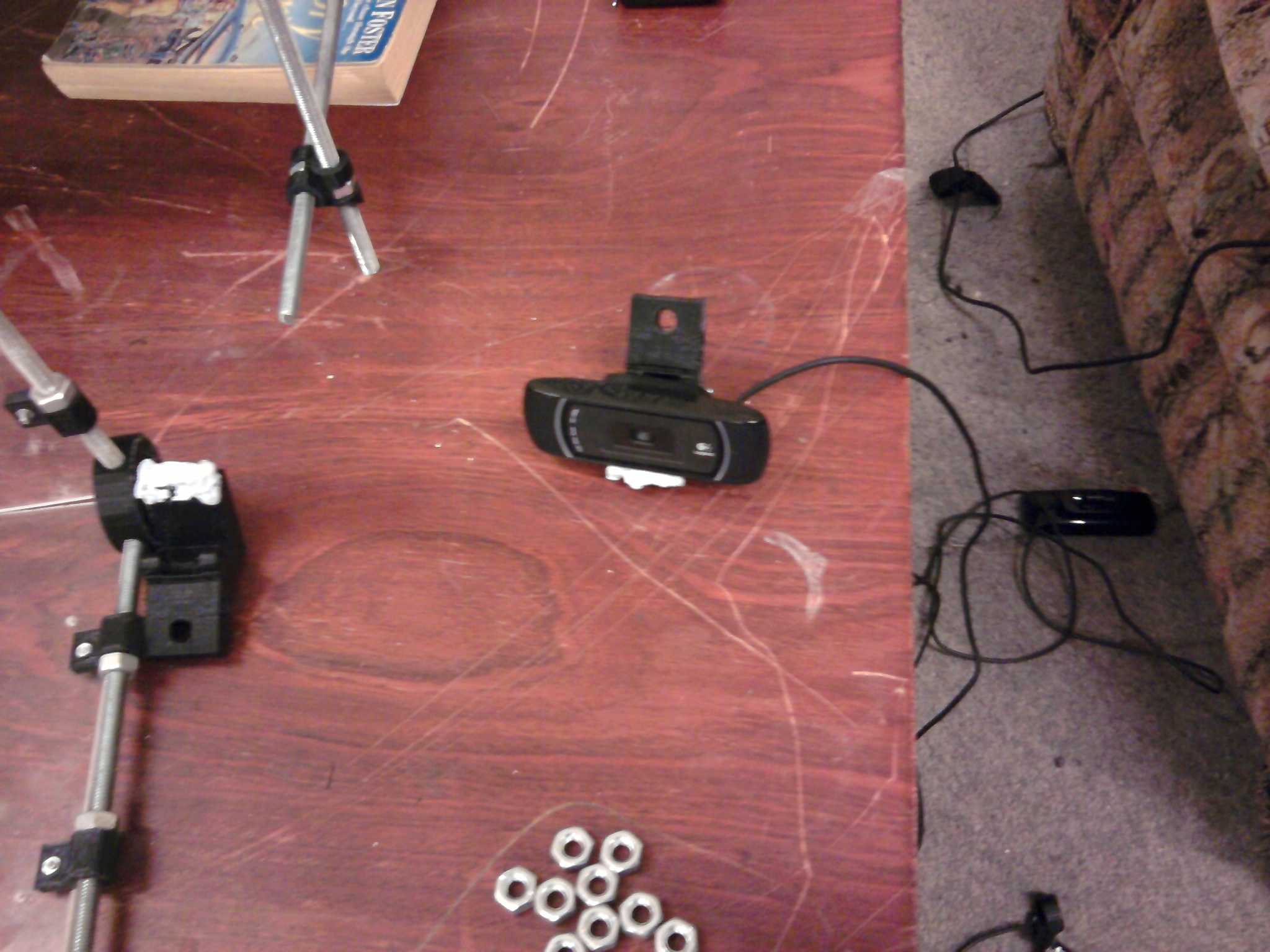
If you follow in my footsteps you can make some substitutions but make sure the webcam you use is UVC standards compliant. It should say it on the box but if not have a look at the USB Video Class Linux device driver homepage for a list of some of the known compliant webcams. The majority of new webcams should be fine but best to check before purchasing anyway. The UVC standard does the same thing for webcams as has happened with USB flash-drives. It used to be that every flash-drive came with its own driver disk but now the majority follow a standard way of addressing them so you only need one driver for lots of different manufacturers flash-drives. The same thing has been happening with webcams for a while now.
The package for my webcam says you can get 10MP image with ‘software enhancement’ which is interpolated from the camera sensor that is 5MP. Its normally quite hard to find the actual resolution before you buy a webcam but from this one point of data it would be reasonable to assume that the actual resolution is half the ‘software enhanced’ value.
Some disadvantages of webcams over standard digital camera to think about
A digital camera will normally be able to take higher resolution images than a webcam and will also have optical zoom whereas the current crop of webcams do not have any optical zoom capabilities – see wikipedia for an explanation of how optical zoom lenses work. This means that there is less flexibility in where you place a webcam.
For the purposes of book-scanning the camera should be placed along a line at 90 degrees to the plane of the book page, the normal to the book plane. The further away you get from the book the less being exactly on the line matters but also the fewer the number of pixels in an image of a given resolution will actually be of the book – this follows an inverse square law i.e. an image taken from twice the distance will have 1/4 the number of pixels representing the book. The exact lower limit for OCR purposes will depend on the size of the page and the size of the text on the page but I would suspect that in general it will be between 1/2 and 2 Mega-pixels. This leads to a lower limit distance that is based on this lower limit and the camera sensor resolution; if you have two cameras with one having 4x the number of pixels as the other, the lower limit distance will be twice as far away.
If you are using a camera with, for example, 2x optical zoom then you can have the camera at twice the standard lower limit distance and get an image of a page using the same number of mega-pixels, or you can place the camera at the standard lower limit distance and get an image where the page covers 4x the number of mega-pixels.
What this means is that for a webcam you are much more limited in where you can put the camera than for a normal digital camera for a number of reasons:
- The lower limit distance for OCR purposes is closer due to the lower resolution of the camera sensor compared to a digital camera.
- The lower limit distance is not able to be extended due to the lack of optical zoom in the camera.
- This leads to a further limitation in that the webcam must be closer to being exactly on the normal line to the book plane.
This converts into a number that you need to know for the post-processing with scantailor (used to take the full colour jpg images and convert them to black/white tifs of just the straightented and dewarped area of interest): dots per inch (dpi) at the book plane. The easiest way to find this number is to take a pair of image, taken with the webcam in the “correct place” and measure how many pixels wide and long the page appears in the images. Then compare it to the physical size of the book and divide them to get an approximate dpi. Scantailor has the potential to handle rectangle pixels by having a different dpi in the x and y directions but normally pixels will be square so you only have to remember the one number. The range of dpi accepted by the current version of scantailor is 150-9999 with presets for 300, 400, and 600. My current setup is approximately 250 dpi, with the webcams mounted on the crossbeams of the upper platen, so it is barely acceptable.
Having said all that, I am using webcams for the simple reason that you can easily attach them to the computer and send them a signal to take a picture which will be automatically transferred to the computer. This compares very favorably to the alternatives you have when using a digital camera. The two standard methods seem to be to use a specific type of camera with a modified firmware or a more general solution whereby a camera is put into a structure that physically pushes the button to take the picture. In both cases the images are stored on SD cards in the camera and need to be taken out later and put on to the computer.
A note on digital pan, tilt, and zoom
Digital pan, tilt, and zoom are all things that you could do yourself with a good image editor and a copy of an image taken at full resolution in a lossless format (e.g. TIFF) so I will describe them in this way.
You can take a portion of the image and crop it to a certain size. Exactly which part of the image you crop is chosen by the pan and tilt characteristics: if you take the center of the image then there is no pan or tilt. If you move this cropping rectangle up or down from the center this is changing the tilt. If you move this cropping rectangle left or right you are panning. This is useful if the image taken at full resolution contains a significant amount of non-book pixels. You can use the pan and tilt at a smaller than full resolution to speed up any further post-processing and so should be used if practical.
Digital zooming on the other hand gives, at best, nothing useful, and, at worst, could produce more errors in the OCR step. This is because a digital zoom takes a certain subset of the pixels and tries to produce an image with a higher number of pixels by interpolating what is between the ones it knows about. In a simple example of a greyscale image where black is represented by 0, white by 255, and levels of grey in-between: if you have two parallel lines, one black and one white, what happens if you add additional pixels in between them? If you add one additional line of pixels they will be a mid-grey level of 127, if you add 2 additional lines of pixels, one will be light grey, 192, and one will be dark grey, 64, and so on. In practice it is more complicated as in the case of the colour images you deal with levels of Red, Green, and Blue, and with other structures other than parallel lines you use some sort of simple weighted average of the pixel colours within a certain radius, normally weighted by the inverse squared distance. But in all cases this is simply a ‘best guess’ based on the available evidence and as such may be wrong. If you don’t have to do it, don’t. If you have the choice between digital zoom or simply moving the camera closer, you should move the camera closer.
I think in a book-scanner setup with a standard digital camera having both optical zoom and digital zoom, you should choose optical zoom over moving closer (due to the additional flexibility of moving further from the exact normal line) and moving closer over digital zoom (due to the ‘best guess’ nature of digital zoom) but I haven’t actually done any experiments to back this up 🙂
The top 3 image sizes that can be captured by my webcams are:
1600×1200 (1.92MP)
2048×1536 (3.1MP)
2592×1944 (5MP) – at this resolution any settings for pan, tilt, zoom etc. are ignored
Software (Linux only)
Eventually I want to have a Windows version as well but I don’t have time at the moment. Some places to look for the parts to put script together:
– Windows alternatives to guvcview
–Tools in the WDK especially the ones under Technology: Audio / Video Drivers
I have written a small shell script to tie together all the different parts of the scanning process: first getting the initial jpeg images with a homemade script, explained below, then using scantailor to get a black/white tif image of each page, then using a number of small utilities to convert this into a djvu or pdf file. In the case of djvu the file will be ocr’d at the same time (although there seems to be a bug that crashes it half the time for me) whereas the pdf will just be images and have to be ocr’d later. Presumably the ocr process would work better with higher resolution sources to work with i.e. higher dpi at the book plane. All the tools can be found in packages for the ubuntu repositories, specifically scantailor, djvulibre-bin, ocrodjvu, and libtiff-tools.
#!/bin/sh
logfile=log.txt
currentjpgfolder=../currentscan
currenttiffolder=../currentscan/out
# 0) Remove old folders
rm -rf $currenttiffolder
rm -rf $currentjpgfolder
mkdir $currentjpgfolder
# 1) Get the initial jpg images with
echo $(date) Starting snapshot process. >> $logfile
./webcamsnapshots.sh $currentjpgfolder
echo $(date) End of snapshot process. >> $logfile
# 2) Clean up and get tif images from
echo $(date) Starting scantailor process. >> $logfile
# Note my setup is approx 250 dpi at the page plane which you need to know to run scantailor
scantailor
echo $(date) End of scantailor process. >> $logfile
# 3) Convert tif images to individual djvu files:
#cd $currenttiffolder
#for i in *tif; do cjb2 $i ${i%tif}djvu; echo $i; done
# 4) bundle djvu files together in one file :
#djvm -c bundle.djvu *djvu
# 5) OCR djvu files
#ocrodjvu -o ocr_bundle.djvu bundle.djvu –language=eng
# There seems to be a bug where it sometimes crashes may be related to this amd64 bug in tesseract https://bugs.launchpad.net/ubuntu/+source/tesseract/+bug/565688
# 6) extract text:
#djvutxt ocr_bundle.djvu > text.txt
#echo $(date) End of tif conversion to djvu process. >> $logfile
#(Easiest way to then convert ocr_bundle.djvu to text/images pdf is through the website http://www.djvu-pdf.com/ )
#Alternatively, pack tif files into multi-page tif and convert to pdf.
cd $currenttiffolder
# Copy tifs to multi-page tif
tiffcp *tif bundle.tif
# Convert to pdf (not ocr’ed)
tiff2pdf -o output.pdf bundle.tif
# Basic ocr capability available at http://www.djvu-pdf.com
echo $(date) End of tif conversion to pdf process. >> $logfile
Scripts for taking webcam jpg images
Note that as at the time of writing the kernel support for UVC devices in Linux does not support Still Image Capture so if you want to do it you need to use a user-land program to do it. In my case I am using a version of uvccapture.
Main webcam snapshot script (Most of the complicated bit is actually in the numbering of the images and adding leading zeros to the number)
#!/bin/bash
#sudo modprobe pcspkr
# Only uncomment if also uncommenting beep command at end. In Ubuntu at least the pcspkr is disabled by default# This requires the standard package guvcview for initial adjustment of camera parameters and the forked version of uvccapture i.e. it won’t work with the standard uvccapture package without changing this script.
logfile=log.txt
runcommand=./uvccapture # Where is the image capture command
pershotsetup=./per-shot-setup.sh # What script do you want to run before each shot, if you don’t want one make a blank executable file and point to it here.
Leftcamera=/dev/video1
Rightcamera=/dev/video2
Leftfileprefix=$1/interleaved
Rightfileprefix=$1/interleaved
#If left and right prefixes are the same they will be numbered so they are interleavedfilesuffix=jpg # This doesn’t change the file format that is saved. It *will* be a jpg image no matter what you name it.
leftwidth=2592
leftheight=1944
rightwidth=2592
rightheight=1944
# These must be valid modes the camera can do.
# You can find out valid modes by looking at the drop down list of the Resolution option under Video and Files tab when running guvcview -d /dev/videoX or from the command line uvcdynctrl -f -d /dev/videoX if you have it installed
# (where /dev/videoX is the camera device above)# You should not need to change anything from here on down
echo $(date) Starting scan. >> $logfile
stime=$(date ‘+%s’)# Initial Steps
InitialStep=1
TotalInitialSteps=2
numberofdigits=4 # 3 would mean you can have up to 999 pages. 4 means you can have 9999 pages
printf -v prefix “%0${numberofdigits}d” # set the prefix to be the correct number of zeros
leftcount=0
rightcount=0echo
echo “Initial Step $InitialStep of $TotalInitialSteps – Initialise settings for the Left Camera.”
echo “Pay particular attention to Focus settings”
read -n 1 -p “Press any key to continue” input
echo
guvcview -d $LeftcameraInitialStep=$((InitialStep + 1))
echo
echo “Initial Step $InitialStep of $TotalInitialSteps – Initialise settings for the Right Camera.”
echo “Pay particular attention to Focus settings”
read -n 1 -p “Press any key to continue” input
echo
guvcview -d $Rightcamera
echo#Snapshot loop
total=0read -n 1 -p “Type any key to take a set of pictures or ‘q’ to quit: ” input
clear
while [ “$input” != “q” ]
do# Take the left camera image
leftcount=$((leftcount + 1))
newnumber=${prefix}${leftcount} # get number, pack with zeros
newnumber=${newnumber:(-$((numberofdigits)))} # the last so many digits$runcommand -d$Leftcamera -x$leftwidth -y$leftheight -o$Leftfileprefix$newnumber.$filesuffix -i$pershotsetup -w
echo $(date) Created file $Rightfileprefix$newnumber.$filesuffix >> $logfile
total=$((total + 1))if [ $Leftfileprefix = $Rightfileprefix ]; then
rightcount=$((leftcount))
leftcount=$((leftcount + 1))
fi# Take the right camera image
rightcount=$((rightcount + 1))
newnumber=${prefix}${rightcount} # get number, pack with zeros
newnumber=${newnumber:(-$((numberofdigits)))} # the last so many digits$runcommand -d$Rightcamera -x$rightwidth -y$rightheight -o$Rightfileprefix$newnumber.$filesuffix -i$pershotsetup -w
echo $(date) Created file $Rightfileprefix$newnumber.$filesuffix >> $logfile
total=$((total + 1))beep
# This gives an audio alert that its finished but can really get on your nerves so commeted out by default.
read -n 1 -p “Type any key to take another set of pictures or ‘q’ to quit: ” input
echo
done#Quit and write a line to the log file
etime=$(date ‘+%s’)
dt=$((etime – stime))
ds=$((dt % 60))
dm=$(((dt / 60) % 60))
dh=$((dt / 3600))echo $(date) Ending scan of $total pages. Time taken: $dh hours, $dm minutes and $ds seconds >> $logfile
The script above stitches together a forked version of uvccapture to do the heavy lifting and the standard package guvcview to set the camera parameters once at the start of the session. It has a few settings for you to set at the top but they are all pretty much self-explanatory. The only thing you may need to change on a semi-regular basis is the width and height of the images to be captured. These must be one of the image sizes supported by the webcam.
If you are also going to use a per-shot initialisation routine to reset camera settings for each image, as I am doing for the focus settings, you will also need uvcdynctrl installed.
Standard uvccapture (i.e. the one you get when you go sudo apt-get install uvccapture) is not optimal if the image to be captured is bigger than 960×720 as that activates YUYV capture which is then recalculated to a subset of standard RGB values when saved as jpg (and also at this point some/all of the non-default camera settings were ignored – I only tested zoom). Note that the standard uvccapture also takes a significantly long time (measurable in seconds rather than tenths of a second) to take a large image, in part because of this conversion but also because it is setting the gain, saturation, contrast, and brightness settings for each image captured.
The forked version of uvccapture came originally from http://dp.nonoo.hu/modified-uvccapture/ and will capture an image in MJPEG mode for all resolutions by default and does not do the resetting of the gain, saturation, contrast, and brightness levels for each image. I have added a -i option for Initialisation command processing (which is passed the camera device as a parameter) and this is now also available at the above link as well. If you need to re-compile, just run ‘make’. If it comes up with an error about missing jpeglib.h, install libgd2-xpm-dev and try it again.
The only setting that was not working with Nonoo’s uvccapture was focus as in my case the lens goes back to its parked state when not in use and when the image is captured it is done from this parked position. So I am using a script that uses uvcdynctrl to read and write the focus settings (read settings as they were before parking, change them then set them back to the recorded settings – if autofocus, wait 2 seconds before continuing). The initial version of this is also available at the above page but the current one is below (referenced as ./per-shot-setup.sh by the above script):
#!/bin/bash
#$1 should be the device that uvccapture is passed as part of it’s command line
device=$1#This is currently needed as my Webcams (Logitech Pro Webcam C910) park the lens when powering down (which will happen after each block of accesses to them to set settings or capture an image) and don’t do any focus changes when just capturing an image.
# Is autofocus set?
autofocus=`uvcdynctrl -d$device -g ‘Focus, Auto’`
# If autofocus is set then set it to manual and then back again.
if [ $autofocus = 1 ]; then
uvcdynctrl -d$device -s ‘Focus, Auto’ 0
uvcdynctrl -d$device -s ‘Focus, Auto’ 1
echo “Allowing autofocus to focus”
sleep 2
else
#The focus is set to manual. Set the focus to zero before resetting it to the extracted value.#Note that for the Logitech HD Pro Webcam C910 the valid focus settings change in steps of 17 (invalid settings between are rounded to the nearest valid one before being set)
# i.e. the only valid settings are 0,17,34,51,68,85,102,119,136,153,170,187,204,221,238,255
#Changing the lens value between 0 and 68 seems to do nothing and I think zero is where the lens parks itself
#So changing the setting to 0 won’t actually make the lens move saving on un-necessary wear and tear.focusvalue=`uvcdynctrl -d$device -g ‘Focus (absolute)’`
interimfocusvalue=0#The focus value set has to be different to the one currently recorded to trigger an update.
# If the focus is already at 0 then to change the focus from the park position to 0 then we need to
# set it to something different first.# However if the park position *is* at 0 then this doesn’t matter. If the park value is not at the zero point the below should be uncommented.
#if [ $focusvalue = 0 ]; then
# interimfocusvalue=255
#fi
# Now change the focus to the interim value and then back to the target valueuvcdynctrl -d$device -s ‘Focus (absolute)’ $interimfocusvalue
uvcdynctrl -d$device -s ‘Focus (absolute)’ $focusvalue
fi
The settings that uvcdynctrl and guvcview can read and write are specific to your webcam but you can list them using the -c option of uvcdynctrl. For my webcam (Logitech HD Pro Webcam C910) you get the following settings:
Zoom, Absolute
Focus, Auto
Focus (absolute)
Tilt (Absolute)
Pan (Absolute)
Exposure, Auto Priority
Exposure (Absolute)
Exposure, Auto
Backlight Compensation
Sharpness
White Balance Temperature
Power Line Frequency
Gain
White Balance Temperature, Auto
Saturation
Contrast
Brightness
Some of these are numbers between 0 and 255, some are 0 or 1 etc. The best idea is to use guvcview to make your initial investigations and adjustments as that will show things as sliders or tick-boxes or, in the case of the possible image sizes, a drop-down list of choices.
I wrote a simple little loop to take 100 5 megapixel images one after the other so I could estimate how long it took and without changing of focus settings it took 50 seconds to do 100 images, whereas with changing the focus to a picked manual setting it took 90 seconds and obviously the auto-focus would be dominated by how long you set the sleep to but in my case 2-3 seconds sleep seems to be enough for auto-focus to do its job.
Prototype Number 1

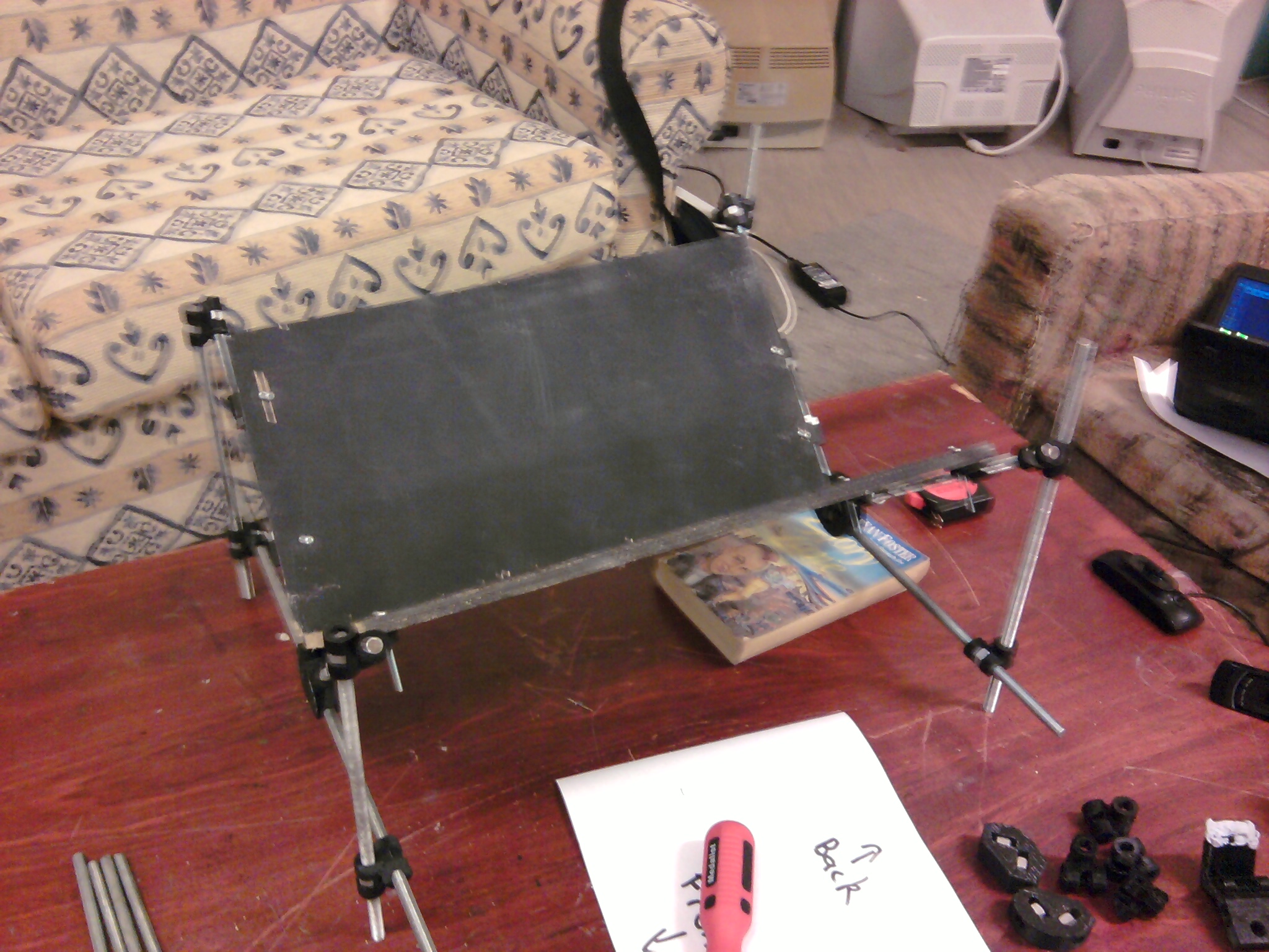
The above image shows prototype number 1. The below image show one image captured from a webcam (compressed for web display) and, as tif images aren’t displayed properly in WordPress, the appropriate tif image can be downloaded from here.

Initial Results for Prototype 1
I did an initial scan of a 300 page book and found that over the course of the scan the webcams slowly rotated out of position around the M8 rod the support was attached to. I finished scanning the book anyway to get an idea of a speed breakdown:
1) Scanning approximately 300 pages manually took approximately 20 minutes (296 pictures taken in 29 minutes and 26 seconds).
2) Processing the 300 jpg images with Scantailor took 1 hour 5 minutes, including the time to automatically de-warp the pages, of which only 2-5 minutes were actually interacting with the program. Everything else was done automatically.
3) Converting the 300 tif images into one compound tif and converting that to an image only pdf took a couple of minutes but there was some sort of memory issue so it may not have finished converting to pdf as the compound tif was 40MB containing 237 pages, and the pdf was only 7MB and could not be opened.
Takeaways
1. The webcam mounts need to be redesigned to be more stable. Probably adding trapped nut holes and using two nuts on each side of the rod would help.
2. The lower platen base attachments should have an additional trapped nut to thread the bottom horizontal bar through for more stability and less wobbling. This will make it slightly harder to pull totally apart.
3. Over the course of scanning a book that has been sitting on a shelf the motion of the upper platen against the pages can lead to a small pile of dust building up and being deposited between the platen.
4. The audible beep after a pair of images is taken is actually really handy to have and should probably be turned on by default.
5. There are far too many nuts that can slowly come loose over the course of a scan. This is good for a prototype that is going to broken down every day but not good for a working machine. The whole thing should be redesigned with more compound parts that are designed to be attached and not taken apart. The disadvantage of this is that to disassemble it you would have to take it apart in the correct order as there is less flexibility of the rods and if you do it in the wrong order it is more likely that you will force one end of a rod that will act as a lever and easily break the printed part attached at the other end.
6. The webcams are barely adequate for the job at the current mount points. They should be either replaced with better ones or the design changed to place them closer to the book planes without interfering with each other.
7. The placement of the top platen changes over the course of the book as the “middle” of the book shifts. The current design is sloppy enough to handle this but it should be redesigned to be able to handle it as a matter of course. Maybe the platen connectors should be redesigned to be parametric and other angles tried as part of this redesign. This is both helped and hindered by the flexibility of the perspex bottom platen so I’m unsure whether to replace this with a proper wooden one or not.
8. When using webcams with various auto light corrections such as I am it doesn’t look like additional lighting is needed during the day if the rig is set up in a room with windows and indirect sunlight. At night, dedicated lighting isn’t needed either, so long as the reflections of the room lights cannot be seen in the platen (although this can take a bit hard depending on the room), indirect lighting is normally enough.
9. The lower platen should not be transparent as then the tiff production and therefore OCR can change depending on what can be seen through it.
10. More testing needs to be done with the post-processing steps to make sure I know what I’m doing and that issues are not because of ignorance.
Prototype number two
[These instructions have not yet been vetted. I think they are right but I will need to go through them with someone.]
3D Printed Parts
There are 5 main OpenSCAD scripts that produce the different parts, available here, along with the STL files for the common configuration of a 90 degree platen:
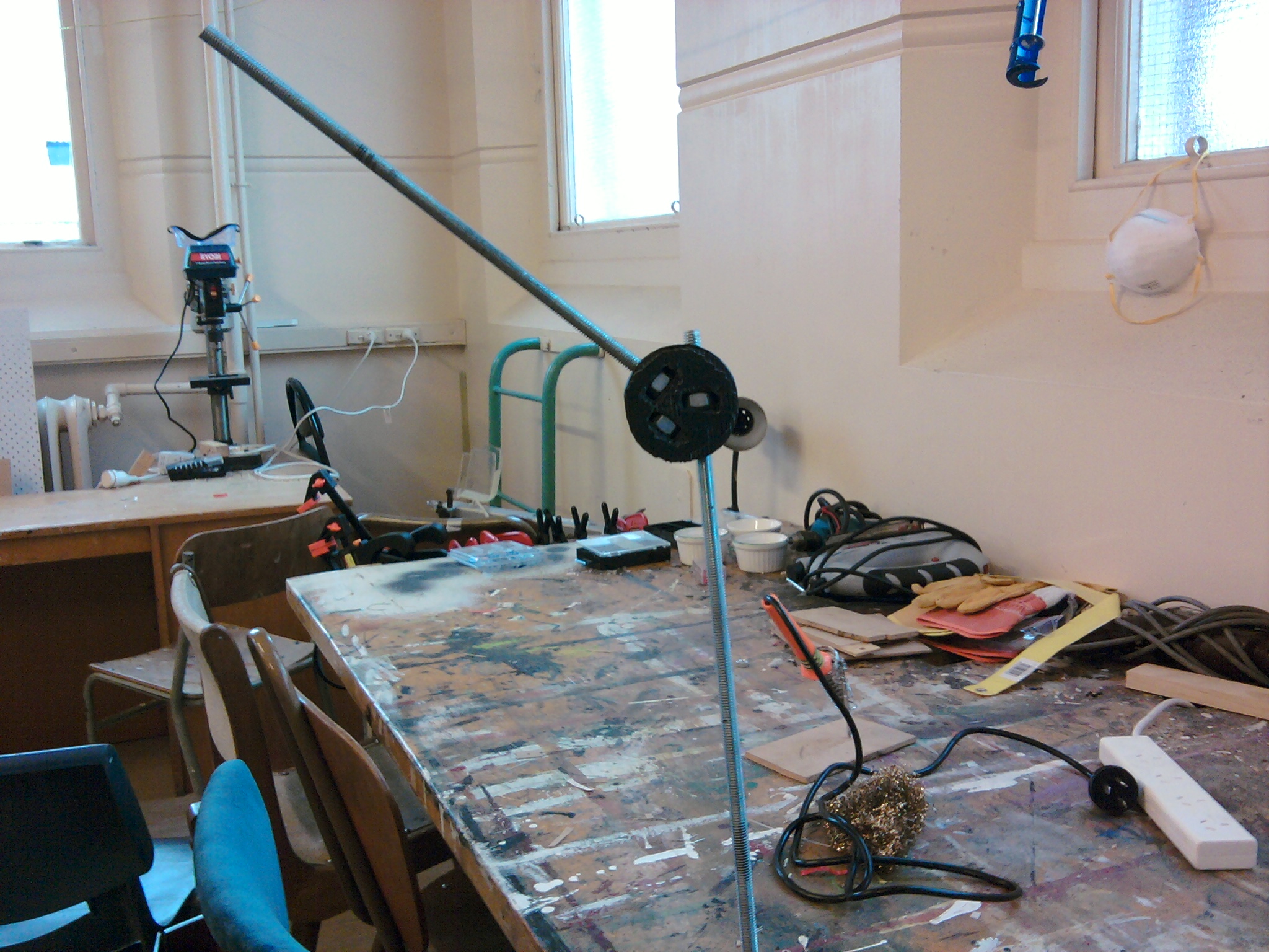
– a rod connector which is parameterised so that the you can choose the diameter of the rod and trapped nut, currently M8, and the angle to attach the rods. This is what is used for most of the connections.
– a part that allows a rod to slide through it and takes a trapped nut with a bolt through the platen to attach the platen to the framework made from the rods. Again parameterised so that you can choose the diameter of the rod and the size of the nut and bolt holes (currently M8 rod and M3 hex nut and bolt.
– a part that allows you to attach the web-cam to the frame of the bookscanner. This would have to be re-designed for a different webcam.
– 2 scripts to produce the upper and lower platen base attachments, with a parameter set in the configuration scad script as to the angle of the platen.
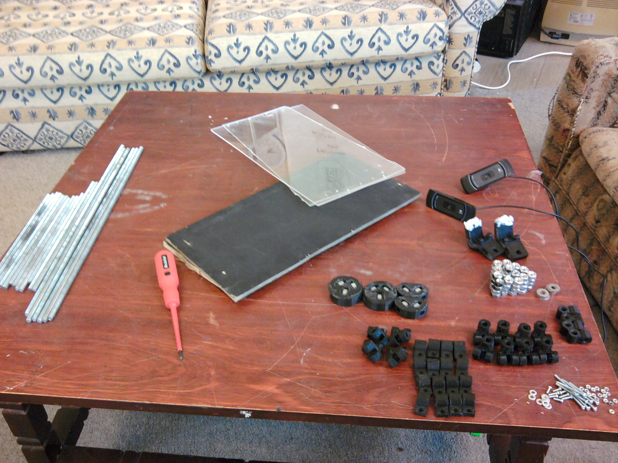
Total parts list
– 16 printed parts of “m3 nut and bolt attachment to through bar”
– 8 printed parts “90 degree bar join”
– 2 printed parts, depends on the angle of the platen. angle/2 degree bar join (for simplicity I’ll call it 45 degree bar join below)
– 2 printed parts, depends on the angle of the platen. 90+angle/2 degree bar join (for simplicity I’ll call it 135 degree bar join below)
– 2 printed parts “lowerplaten connector”
– 2 printed parts “upperplaten connector”
– 4 printed parts “90 degree bar join (no trapped nut)”
– 2 printed parts “camera_mount(Logitech C910 webcam)”
– 6 500mm lengths of M8 threaded rod (4 can be as short as 400mm with the other two having to be approximately 450mm)
– 10 250mm lengths of M8 threaded rod
– 2 300mm lengths of M8 threaded rod
– 10-14 M8 washers
– 68-72 M8 hex nuts
– 2 M8 Nyloc hex nuts, or 4 more standard M8 hex nuts
– 2 wooden lower platen (cut to 400mmx200mm at the moment – the lengths should be as close as possible)
– 2 acrylic perspex upper platen (cut to 400mmx200mm at the moment – the lengths should be as close as possible. If the wood and perspex are different, the perspex can be bigger but not smaller than the wooden lower platen)
– 18 M3 hex nuts
– 8 M3 bolts (length dependent on thickness of perspex platen)
– 2 M3 bolts (long)
– 8 M3 bolts (length dependent on thickness of wooden platen)
– 2 Logitech C910 webcams. I bought mine at PBTech for $250.70 each (unfortunately, at 5MP resolution, the highest I could find, they are only border-line useful)
– some blu-tack
Assembly (approximately 3 hours)
Step 1: The lower platen (1 hour)
Partial Parts List:
– 2 wooden lower platen (cut to 400mmx200mm at the moment – the lengths should be as close as possible)
– 4 250mm lengths of M8 threaded rod
– 2 500mm lengths of M8 threaded rod (can be 400mm)
– 8 M3 bolts (length dependent on thickness of wooden platen)
– 8 M3 hex nuts
– 14 M8 hex nuts
– 8 printed parts of “m3 nut and bolt attachment to through bar”
– 2 printed parts of “lowerplaten connector”
Take one of the lower-platen connectors, insert the trapped nuts and attach the longer through rod first. The easiest way may be to hold the through rod vertically in a vice, attach a short rod to the connector, then wind the connector+nut on to the rod held in the vice. This gives you a handle to use when winding the connector onto the rod. Wind it so that the connector is as close to half way along the rod as possible.
Once the connector is about half way along add the other trapped nuts and then attach two of the shorter rods by screwing them in. Do this for both lower-platen connectors.
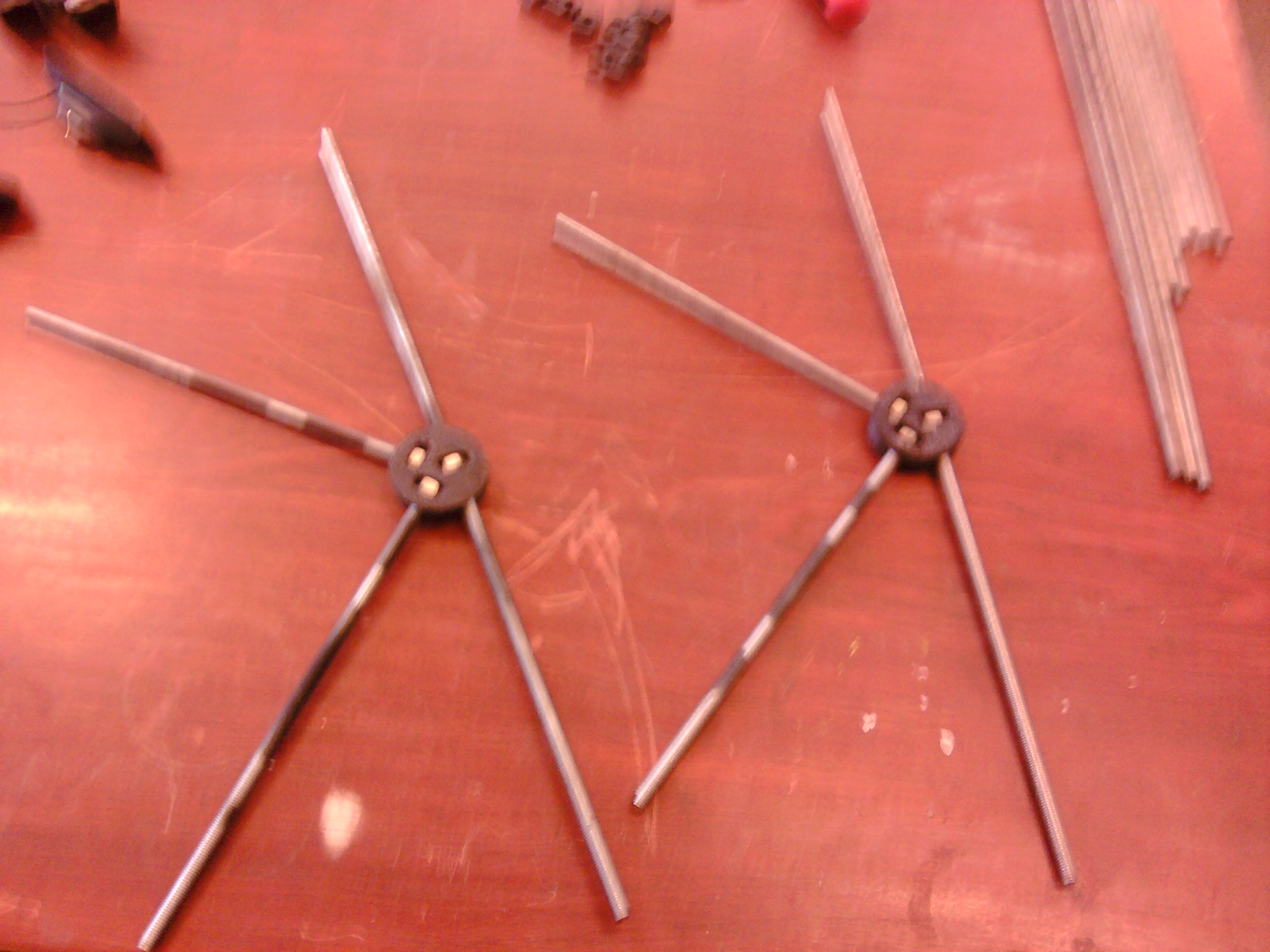
For each of the four 250mm rods add, in order:
– 1 printed “m3 nut and bolt attachment to through bar”
– 2 hex nuts
– 1 printed “m3 nut and bolt attachment to through bar”
Add the printed parts so that when the connectors are balanced in the final V configuration the flat side of the piece is pointing upwards and inwards. This is where you choose which of the connectors is at the front and which is at the back.
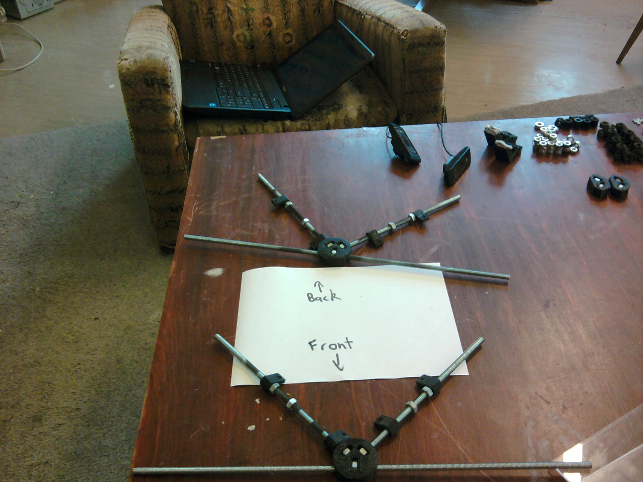
Attach the wooden lower platen to both short rod connectors at one end first. Then you can line up where to put the holes for the other end more accurately (taking into account any issues due to uneven cutting of the wood). Holes for the bolts can be drilled by lining up where the printed connector is to be attached and (using a low/battery powered 2mm bit) drill through the 3mm hole in the plastic. Once the holes are initially drilled they can be drilled out to 3mm with a different bit. (Another larger bit could also be used to drill part way through the wood for an inset for the bolt head.) Attach the bolts with the head on the upper side of the wood and the screw attached to fit into the hole for it. The M8 hex nuts are used to mark the correct placement of the attachment connectors so that the wood from both sides meets in the middle.
Do the same thing at the other end. This requires a bit more effort so that everything is lined up so that the V made by the wood is without gaps where the wood meets.
Step 2: Add the leg-support rods (40 minutes)
Partial Parts List:
– 16 M8 hex nuts
– 4 printed parts “90 degree bar join”
– 2 printed parts, depends on the angle of the platen. angle/2 degree bar join (for simplicity I’ll call it 45 degree bar join below)
– 2 printed parts, depends on the angle of the platen. 90+angle/2 degree bar join (for simplicity I’ll call it 135 degree bar join below)
– 2 250mm lengths of M8 threaded rod
– 2 300mm lengths of M8 threaded rod
Add the trapped nuts to the bar joins, two per joining part. At each end use one of the 45 and one of the 135 degree bar joins to attach to the top of the V and line up so that the empty join is vertical and on the outside.
Turn upside down and add the 90 degree bar joins at each end of the horizontal rods and wind them on until they are approximately in the correct position i.e. directly below the 45 and 135 degree bar joins.
Add the vertical rods, the shorter pair at the front, the longer pair at the back. The easiest way is to feed the rods into the bottom, to the point where there is enough to feed through that the top of the rod is lower than the bottom of the plastic for the 45 and 135 degree bar joins. This means everything can be lined up, then the rod can be fed back into the top join.
For the front rods, the rods should not poke up above the plastic of the top join piece meaning there is approximately 50mm clearance at the bottom. For the back rods to have the same ground clearance (i.e. the platen is level) there should be approximately 50mm above the top of the plastic joining rods. The more length above the back joining pieces, the larger the book that can be scanned. This is easiest done by initially having the platen upside down, inserting the front rods and inserting the back rods, flipping it onto its edge to get the approximate correct length, and then putting it right side up to do the final evening out of the length of the legs.
Step 3: The upper platen (45 minutes)
Partial Parts List:
– 2 acrylic perspex upper platen (cut to 400mmx200mm at the moment – the lengths should be as close as possible. If the wood and perspex are different, the perspex can be bigger but not smaller than the wooden lower platen)
– 4 250mm lengths of M8 threaded rod
– 8 M3 bolts (length dependent on thickness of perspex platen)
– 8 M3 hex nuts
– 16 M8 hex nuts
– 8 printed parts of “m3 nut and bolt attachment to through bar”
– 2 printed parts of “upperplaten connector”
– 4 printed parts “90 degree bar join”
Add the trapped nuts to the upperplaten connecter and screw in the 4 250mm rods. As with the lower platen, for each of the four 250mm rods add, in order:
– 1 printed “m3 nut and bolt attachment to through bar”
– 2 hex nuts
– 1 printed “m3 nut and bolt attachment to through bar”
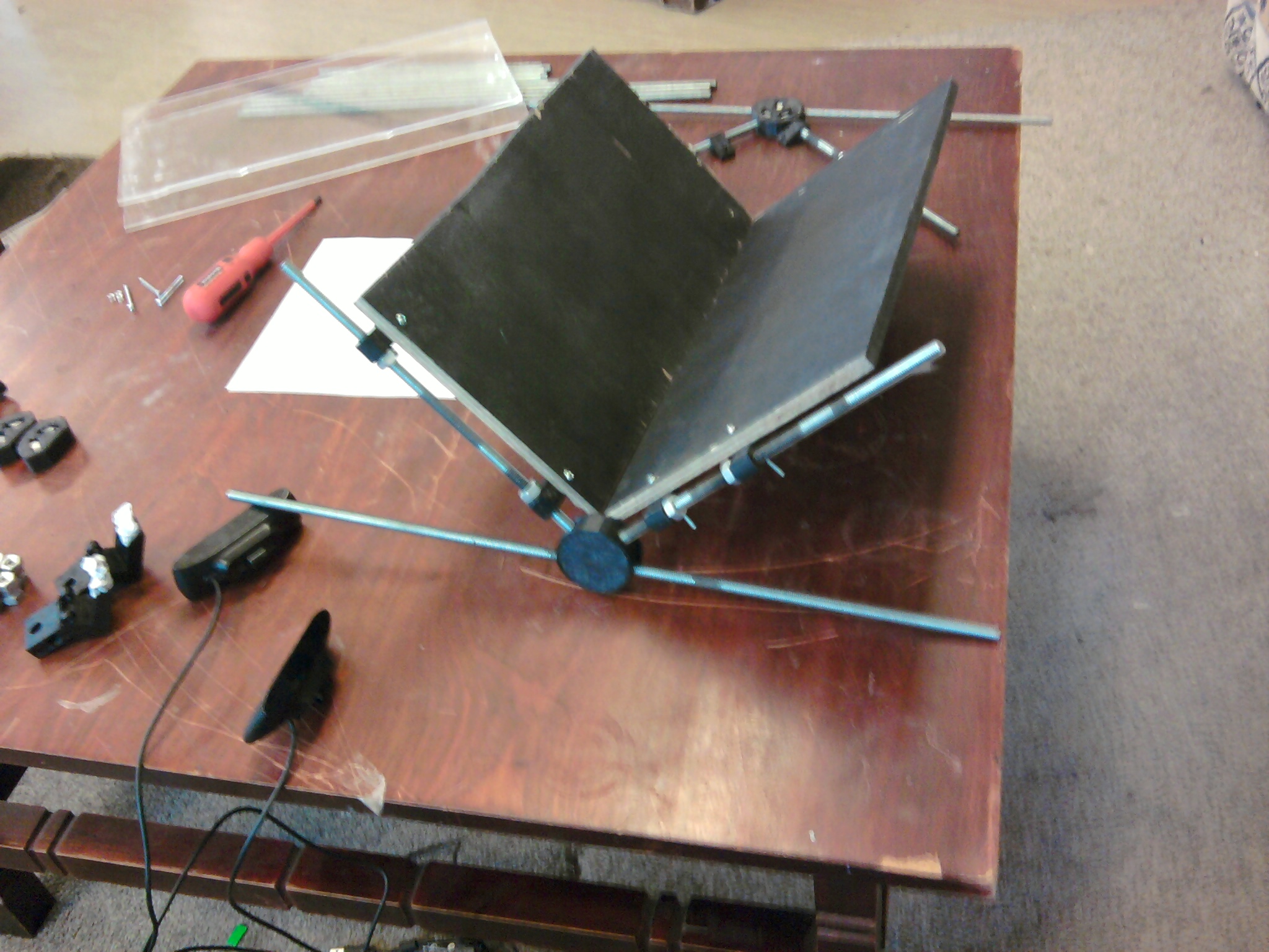
But, in this case, add the printed parts so that when the connectors are balanced in the final V configuration the flat side of the piece is pointing downwards (not upwards as for the lower plasten) and inwards. Attach the perspex upper platen to both rod connectors at one end first. Then you can line up where to put the holes for the other end more accurately (taking into account any issues due to uneven cutting of the perspex). Attach the bolts with the head on the *lower* side of the perspex and the screw attached to fit into the hole for it. The M8 hex nuts are used to mark the correct placement of the attachment connectors so that the perspex from both sides meets in the middle.
Do the same thing at the other end. This requires a bit more effort so that everything is lined up so that the V made by the perspex is without gaps.
Finally, attach a “90 degree bar join” to the top of each of the 4 250mm rods using 4 M8 hex nuts entered in the holes for the trapped nuts.
Step 4: Attach the cameras (30 minutes)
Partial Parts List:
– 3 500mm lengths of M8 threaded rod (one can be as short as 400mm with the other two having to be approximately 450mm)
– 12 M8 hex nuts
– 8 M8 washers
– 2 Logitech C910 webcams
– 2 printed parts “camera_mount(Logitech C910 webcam)”
– 2 M3 hex nuts
– 2 M3 bolts (long)
– some blu-tack
Take each camera and disassemble the camera from the mounting. The easiest way is to take a hacksaw to the rotating hinge part, cut it most of the way through on both sides and then get in with a screwdriver and split it apart.
[ Add photo here]
This should leave the camera attached only to the middle part of the hinge which has a hole in it the an M3 bolt can fit through. Attach the cameras to the camera mounts with an M3 bolt and hex nut (inserted into the trapped nut hole). Note the printed part is designed to have a 1mm square tower between the two parts where the bolt goes through. This is simply support material that can be snipped off after printing. Blu-tack can be added at this point to attach the lower part of the camera to the support.
For each camera mount, put an M8 threaded rod through the lower hole to approximately the halfway point. Put a washer on each end and then screw a nut on each end as well. Don’t worry about screwing the nuts to the middle yet. Add the missing trapped nuts to the “90 degree bar join” pieces at the tops of the upper platen V rods and attach the camera mounts to the upper platen using these threaded rods and trapped nuts.
The easiest way to do this is to first adjust the bar joins by screwing them on to the upper platen rods so that the join holes are parallel (and the distance between the bar joins and the top of the perspex is the same as the base of the camera mount. Pick one end, rotate the join out of parallel and fed the rod in from the middle of the upper platen until the join can be rotated back into parallel and then fed through the other end. Do this to both rods so that the extra 50-150mm is poking out the same end.
Adjust the camera mounts to be parallel (you can test this by putting the M8 rod through the 2 top holes in the camera mounts) and then attach the camera mounts to the top of the perspex with blu-tac. Screw the nuts on the camera mount through-beams so that the washers also clamp the mount in place.
Screw two M8 nuts to the centre of the other 500mm rod and then put a washer on each end. Feed the rod from the centre through one of the camera mounts and then back it through the other. Attach another washer and nut to each end. Now tighten the nuts so that the camera mounts are clamped in this directon as well. This gives additional support but should only be done if the lighting conditions in the final resting place for the scanner are appropriate. For example, if there is overhead lighting, it is likely that this additional support will cast a shadow on the pages to be scanned making it harder for the OCR procedure to process the images.
Step 5: Attach the upper and lower platen (10 minutes)
Partial Parts List:
– 4 printed parts “90 degree bar join (no trapped nut)”
– 1 500mm M8 threaded rod (can be 400mm)
– 2-6 M8 washers
– 2-6 M8 hex nuts
– 2 M8 Nyloc hex nuts, or 4 more standard M8 hex nuts
Screw a nut and then a washer on to the top of the longer vertical rods at the back of the lower platen (initially screw the nuts down to the bar joins).
Thread all 4 printed parts on to the new threaded rod with a Nyloc nut (or two M8 hex nuts that can be tightened against each each other) at each end. Attach this threaded rod to the lower platen by spacing the outer bar joins so they fit over the longer back vertical rods. Note that the horizontal rod should be attached to the inside of the lower platen vertical rods.
Finish this off by adding another washer and then nut to each of these vertical rods (not really needed but it is just tidy. Initially just leave the nut screwed on at the top of the vertical rods).
The upper platen can now be connected via this bar by the inner bar joins. This does not need any extra nuts holding it in place either but some can be added if you like.
The upper and lower platen are now connected and the rod we just added acts as a hinge. The bar joins we’ve just added are currently sliding around allowing a lot of variability for thicker books. If this is not needed the nuts can be tightened.
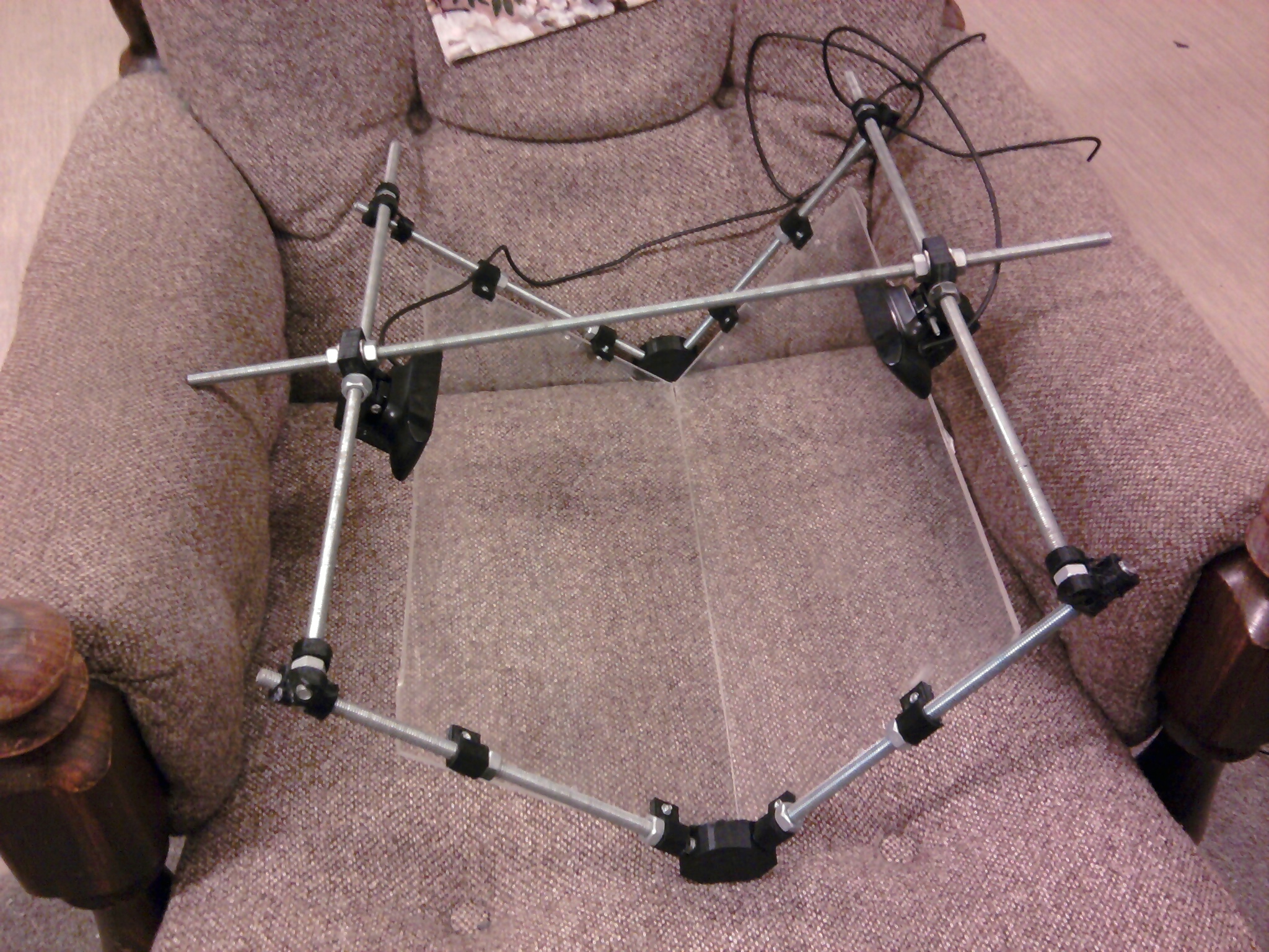
Vertical variability is useful for allowing the upper platen to move up for thicker books and so changes where the V is parallel. Horizontal variability is useful for moving where the V comes down as the exact place where the V needs to come down to split pages changes as you go through the book. In my experience you can get away without this variability for books of less than approx 200 pages and have a less wobbly machine but for longer works you should leave this variability in.
Possible Improvements
- The bar join printed parts with holes for the trapped nuts could be redesigned to be more sturdy. This could either be a larger outer radius or simply rotating the hole for the trapped nuts by 30 degrees so that the holes for the trapped nuts are not flat on the bottom.
Ummm …. as someone who specialises in IT/IP law I’d just like to delicately point out that you (or potential users) may be entering some murky legal waters. Copyright law has penalities for what they call contributory infringement, there are guidelines as to what portion of a published work is allowed to be excepted under “Fair Dealings” and some specific context (eg space shifting).
It’s a great project and I think with a little bit of foresight it can skirt the legal boundaries without anyone getting hit by a lawsuit. I know the mantra of “information wants to be free” sounds good but whilst people can do whatever they want with their creative spark (libre), that ends when you commit an economic tort (non-gratis). The meatSpace analogy is that you are free to swing your arm but that stops at my nose (at least without dire consequences).
I’m happy to give a talk about creative commons anytime …
Nice project.
I like the 90deg pieces of glass – that is soo much nicer for the book spines! (I had been thinking of suggesting you put the cameras underneath a glass coffee table and just spread the books face down on the top surface, but this would not be good for the books, especially paperbacks!).
If I may suggest, why not continue using the two plates of glass in a 90deg configuration. But instead of a V-configuration why not use them in an A-configuration, with the cameras inside. This will make it easy to turn pages, and gravity will keep the book pressed down into the saddle so to say.
I can imagine a sleek black desktop device, made with smoky glass, shaped like a mini A-frame house. If you put infrared LED illumination in you can also avoid blinding the operator. But it would be tricky to install everything so that the LED sources will not reflect glare at a camera.
Good luck.
Peter
Following on from that, why not just have a single camera at the base of the A-frame device, facing upwards into a triangular cross shape prism. The left half of the image would be a mirror image of the right side of the book, and vice versa.
A
/ \
/ A \
/ C \
(Top A = top of a-frame, middle A = prism, C= camera facing up).
Interesting idea. I probably won’t do anything with it as I’ve just about finished my 2nd prototype and it seems to work alright. Assuming a cheap prism, the cost of the whole thing would be a lot less with only one camera but having the book on the top of the A frame rather than at the bottom of a V means that turning a page is possibly harder.
The way I see it you’d pick up the book, turn the page, and put it back down. At the moment that is harder than lifting the upper platen, turning the page, and putting the platen back down. The big problem is always “how do you turn the page?”. Also, I think the scantailor software basically assumes you are scanning one page per image. But the idea of using mirrors so that only one camera is needed is something I’ll look into for the future.
(The 2nd prototype also has a relatively simple way to change the angle you have the book open at by changing a variable and printing off different connectors – although I’ve only tested 90 and 120 degrees).
Yes, turning a heavy crumbling hardback book will be a bit hard on it.
Paperbacks less so of course.
Of course with the prism system you’d have to flick each image horizontally before processing,
In the end, the less parts…
sorry, your forum software does not save spaces as I save them.