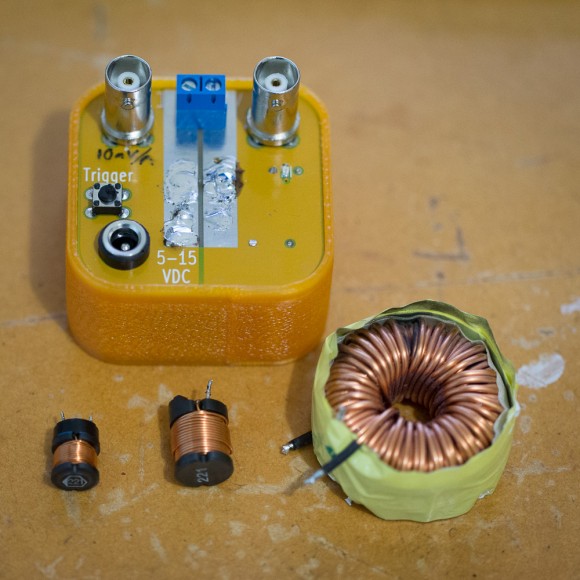
A few weeks back, we had a talk on KiCad (presentation available at http://ianrrees.github.io/KiCad_talk/ ) where we ordered some PCBs to make an inductor tester (Henryometer?) from dirty PCBs. Those boards came in this week, and a few folks have already put theirs together. This post aims to be a quick guide to the usage of the tester; if you’d like to build one yourself just let Ian know, parts cost is $15. You’ll need an oscilloscope and a current-limited DC power supply to make use of it.
Connections between the tester and oscilloscope are made via standard BNC coaxial cables (available via aliexpress for a dollar or two – very handy). The “I” connector gives a voltage that is proportional to the current through the inductor – it gives negative 10mV per Amp. The “V” connector is the voltage across the inductor. DC power is supplied to the tester via the barrel connector, 10V will make some of the math work out nicely. An inductor can either be connected directly to the screw terminals, or soldered on to the exposed pads of the tester. Longer wires to the inductor will affect measurements, so you want to make the connection between inductor and tester as direct as possible.
Once the trigger button is pushed, the tester tries to apply a constant voltage step to the inductor under test, and allows for measurement of the current induced. The I-V characteristic of an inductor can be expressed as V=L di/dt ; we’re applying a known V and measuring di/dt, which gives the inductance L. In the following scope screen shots, the yellow trace is the current and the blue trace is voltage, units are shown in the bottom-left and timebase is on the top.
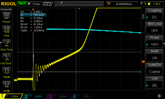
An example from the scope with the leftmost inductor in the picture above. Ignoring that the inductance is printed on top, we can calculate it! The cursors are adjusted to measure the initial slope of the current, ignoring the initial ringing due to parasitics in the tester circuit (try to imagine the line is straight) V = 10 Volts (the channel 2 baseline is inconveniently hidden behind channel 1), di/dt = 1.920 Amps / 0.0000416 seconds. Doing a little division, we get L = 0.000217 Henries – pretty close to the 220 microhenries indicated on the label!
So what’s the difference between the two inductors with the “221” on top – one is clearly bigger than the other – and what is the “knee” in the middle of the screen capture? Let’s first measure the bigger “221” inductor.
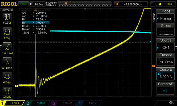
The bigger inductor has a measured inductance 202 microhenries (typical inductor tolerance is +/-10% and I could’ve adjusted the cursors better…), but the knee is now at about 4A.
The knee is the inductor core saturating at roughly 3A for the smaller inductor and 4A for the larger inductor. At currents higher than the saturation point, the inductor exhibits a lower inductance because the core isn’t contributing any more magnetism. Depending on the application, the saturation point can be a limitation or a desirable property.
To close, let’s discuss a measurement of the big toroidal inductor in the top photo, note the scale is different to the earlier screenshots – the top of this curve is about 75 Amps.
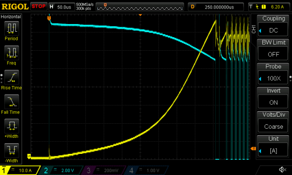
What’s that junk on the right? Short answer is that it’s a design fault in the tester. I made this design in a bit of a rush, and failed to consider an important aspect of the 555 timer we use to set the pulse duration and debounce the trigger button. As long as the trigger button is depressed (a long time in context of this circuit), the output is continually triggered. This results in the current limiting circuit continually oscillating as long as the button is held down and power is available – not so flash. If I make another version of this project, I’ll rework the circuit to only trigger once per push!
The screenshot also illustrates the reason behind the second BNC that measures the output voltage. You may have noticed in the first two screen grabs that we didn’t actually use the blue trace for calculations, but this last shot shows a clear decrease in voltage to about 75% of the initial value before the current limit kicks in. The blue trace warns us that the voltage isn’t constant through our measurement, so more involved math is required to determine parameters of the inductor.